Leave a comment

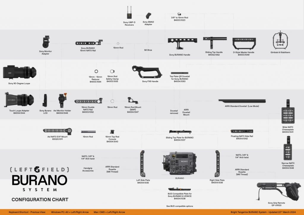
Touch Loupe for Sony BURANO Instructions

In the box

  • Touch Loupe Adapter
  • Lever Lock
  • Dome Nut
  • Hinge
  • Light Seal (four pieces)
  • T8 Key
  • Interchangeable Low Profile Lock

Additional Tools Required

  • Small Philips screwdriver

Touch Loupe Installation

To install the Touch Loupe for the Sony BURANO, begin by detaching the 90-degree adapter from the Sony BURANO loupe.

Using the included T8 tool, remove the four screws securing the adapter to the eye piece.

Insert the straight adapter, ensuring alignment of the four notches, and secure it in place using the same screws.

Installing the light seal

Included with the adapter is an adhesive light seal. There are four pieces to attach, and sit flush to the LCD screen.

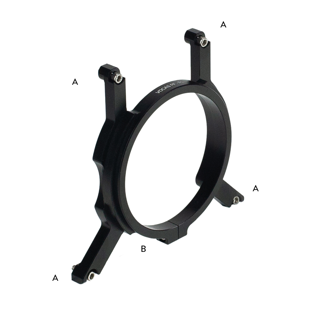
Mounting the Touch Loupe to the LCD

Next, attach the hinge to the top of the LCD screen. You can then connect touch loupe, interlocking with the hinge.

To secure the hinge, thread through the locking lever, connecting the dome nut on the other end. Tighten with the small Philips screwdriver. Once the screw has engaged, pull the lever and tighten to fully secure.

Installing the space saving screw or ratchet lock

These accessories are designed to provide a secure and convenient solution, you can use either a
ratchet lock lever or space saving screw.

Step 1: Remove existing Ratchet Lock Lever
Remove the existing lock lever from your accessory. Use a screwdriver or other appropriate tool to
unscrew it.
Step 2: Insert the Interchangeable Space Saving Screw ( DIN 912 M4 x 14 or 16 ) and tighten it.
Use a HEX T Bar or Allen Key size 3 to tighten the screw. Do not over-tighten the screw.
If you want to switch back to the ratchet lock lever, simply follow the steps in reverse.
If you have any questions or concerns, please contact our customer support team for assistance.
[email protected]

Note: This instruction manual is only for the installation of the Space Saving Screw and Ratchet Lock
Lever. For the use of the accessory, please refer to the product’s instructions.

Leave a comment

Configuration Overviews

burano configuration

To help you get your filmmaking gear up and running, we’ve put together some handy configuration guides. These visual guides quickly show you how everything fits together and which third-party accessories will play nice with your equipment.

Matte Boxes

Misfit Kick Mk II

Misfit Kick 360 Mk II

Misfit Six

Prodigy Air Deflector

Connecting your matte box

Misfit Kick Mk I

Misfit Kick 360 Mk I

RED Cameras

RED V-RAPTOR

Sony Cameras

Sony BURANO

Sony FX6

Sony VENICE 1 & 2

Leave a comment

Sony BURANO Configuration Overview

burano configuration

The Sony BURANO offers a versatile configuration to suit various filmmaking styles. For documentary filmmakers who often work alone, adaptability is key; a comfortable shoulder rig is essential for all-day filming. Conversely, in a studio setting, opting for a robust baseplate on ARRI dovetails allows for swift transitions to gimbals, enhancing efficiency and stability.

To assist with setting up your Sony BURANO rig, we’ve created detailed configuration guides. These visual overviews succinctly demonstrate how components connect and show compatibility with third-party accessories.

The configuration overviews for the Sony BURANO has been separated into three parts for clarity.

Click to download & view high-res PDF

Bright TangerineLeftField Sony BURANO System Cage Top Section 1
Page 1 – The core cage, handle & monitor mounting options
Bright TangerineLeftField Sony BURANO Systme BUD Base Section
Page 2 – BUD Compatible options including the 15mm LWS Baseplate & VCT-14 Shoulder Rig
Bright TangerineLeftField Sony BURANO Systme BUD Base Section ARRI Compatible
Page 3 – BUD Compatible options from ARRI

Installation guide for RED KOMODO Metabones RF-PL Adapter Support

komodo lens adapter support 04

The RF mount on the Komodo is a sprung mount system, and relies on small springs inside the mount to pull the adapter into the right place.

If the adapter support is installed incorrectly, it can result in the lens adapter being pushed or tilted in the wrong direction, which can result in focus and other optical issues.

B4002 1021 RED Komodo Metabones RF PL Support 04 web
B4002.1021 RED KOMODO Metabones RF-PL Support

The following installation sequence must be followed in order to ensure that the adapter is supported correctly on the camera body.

B4002.1021 RED KOMODO Metabones RF-PL Support is not compatible with Metabones Canon EF Lens to RF-mount T Speed Booster® ULTRA 0.71x (EOS R).

B4002 1021 RED Komodo Metabones RF PL Support label
Metabones RF-PL Support

Required Tools

You will need to use a 2.5mm Hex Key.

A – Mount Screw – M3x10mm – 2.5mm Hex
B – Clamp Screw – M3x10mm – 2.5mm Hex

mb pl efr bt1 fs
Remove the tripod foot with the 2.5mm Hex key

Installation Steps

Step 1

Prepare the RED Komodo with the required plates. Ensure all the plates are secured and tight.

Step 2

Remove the Metabones tripod foot by loosening the two screws with the 2.5mm Hex Key.

Step 3

Using a 2.5mm Hex key, mount the support to the camera using the four screws (A) but do not tighten fully at this point.

Step 4

Install the lens adapter into the camera, allowing it to twist onto the camera body and click into place.

Step 5

Using the 2.5mm Hex key, gently tighten the clamping screw (B) on the support so that it starts to hold onto the adapter.

Step 6

Tighten up the mounting screws (A) on the side & top plate in a criss-cross pattern.

Step 7

Fully tighten the clamp screw (B) on the adapter support.

Step 8

To remove the support. First, loosen the clamp screw (B) before loosening the mounting screws (A) on the side & top plate.

Installation guide for RED KOMODO Canon 0.71x Expander Support

komodo lens adapter support 02

The RF mount on the Komodo is a sprung mount system, and relies on small springs inside the mount to pull the adapter into the right place.

If the adapter support is installed incorrectly, it can result in the lens adapter being pushed or tilted in the wrong direction, which can result in focus and other optical issues.

B4002 1026 RED Komodo Canon Support 02 web
B4002.1026 RED Komodo Canon RF 0.71x Expander Support

The following installation sequence must be followed in order to ensure that the adapter is supported correctly on the camera body.

B4002 1026 RED Komodo Canon 0 71x Expander Support label
Canon 0.71x Expander Support

Required Tools

You will need to use a 2.5mm Hex Key.

A – Mount Screw – M3x10mm – 2.5mm Hex
B – Support Screw – M3x6mm – 2.5mm Hex

Installation Steps

Step 1

Prepare the RED Komodo with the required plates. Ensure all the plates are secured and tight.

Step 2

Install the Canon adapter into the camera, allowing it to twist onto the camera body and click into place.

Step 3

Present the support to the Canon adapter. Using the 2.5mm hex key, mount the shorter support crews (B) into the mounting holes on the adapter but do not tighten fully

Step 4

Insert the longer mount screws (A) and secure the adapter to the side & top plates.

Step 5

Tighten up the mounting screws (A) finger tight, and then tighten all screws fully using a criss-cross pattern, including the support screws.

Step 6

To remove the support. First, loosen the mounting screws (A) before loosening the two captive screws (B) on the bottom of the adapter.

Installation guide for RED KOMODO Kippertie RF Support

komodo lens adapter support 03

The RF mount on the Komodo is a sprung mount system, and relies on small springs inside the mount to pull the adapter into the right place.

If the adapter support is installed incorrectly, it can result in the lens adapter being pushed or tilted in the wrong direction, which can result in focus and other optical issues.

B4002 1020 RED Komodo Kippertie Revolva Adapta RF PL Support 04 web
B4002.1020 RED KOMODO Kippertie Revolva & Adapta RF Support

The following installation sequence must be followed in order to ensure that the adapter is supported correctly on the camera body.

B4002 1020 RED Komodo Kippertie Revolva Adapta RF PL Support label
Mount & clamp screws for the Kippertie Revolva & Adapta support

Required Tools

You will need to use a 2.5mm Hex Key.

A – Mount Screw – M3x10mm – 2.5mm Hex
B – Captive Screw – M3 – 2.5mm Hex

Installation Steps

Step 1

Prepare the RED Komodo with the required plates. Ensure all the plates are secured and tight.

Step 2

Install the Kippertie adapter into the camera, allowing it to twist onto the camera body and click into place.

Step 3

Align the support to the Kippertie adapter, ensuring that the arm is on the left side. Using the 2.5mm hex key, connect the two M3 captive screws (B) into the mounting holes on the bottom of the adapter. Do not tighten fully at this point.

Step 4

Insert & secure the mounting screws (A) on the side & top plate in a criss-cross patern, while also tightening up the bottom captive screws (B).

Step 5

To remove the support. First, loosen the mounting screws (A) before loosening the two captive screws (B) on the bottom of the adapter.

Installation guide for RED KOMODO Vocas RF-PL Support

komodo lens adapter support

The RF mount on the Komodo is a sprung mount system and relies on small springs inside the mount to pull the adapter into the right place.

If the adapter support is installed incorrectly, it can result in the lens adapter being pushed or tilted in the wrong direction, which can result in focus and other optical issues.

B4002 1019 RED Komodo Vocas RF PL Support 03 web
B4002.1019 – RED KOMODO Vocas RF-PL Adapter Support

The following installation sequence must be followed in order to ensure that the adapter is supported correctly on the camera body.

B4002 1019 RED Komodo Vocas RF PL Support label
Vocas RF-PL Support

Required Tools

You will need to use a 2.5mm Hex Key.

A – Mount Screw – M3x10mm – 2.5mm Hex
B – Clamp Screw – M3x10mm – 2.5mm Hex

Installation Steps

Step 1

Prepare the RED Komodo with the required plates. Ensure all the plates are secured and tight.

Step 2

Using a 2.5mm Hex key, mount the support to the camera using the four screws (A) but do not tighten fully at this point.

Step 3

Install the lens adapter into the camera, allowing it to twist onto the camera body and click into place.

Step 4

Using the 2.5mm Hex key, gently tighten the clamping screw (B) on the support so that it starts to hold onto the adapter.

Step 5

Tighten up the mounting screws (A) on the side & top plate in a criss-cross pattern.

Step 6

Fully tighten the clamp screw (B) on the adapter support.

Step 7

To remove the support. First, loosen the clamp screw (B) before loosening the mounting screws (A) on the side & top plate.